Guide
Jumper leads vs FFC — choosing conductor geometry
When to use laminated flexible flat cable versus round or flat jumper leads — flex life, pitch, assembly, and how SEPM-class Flat Component notes describe both geometries.
13 August 2026
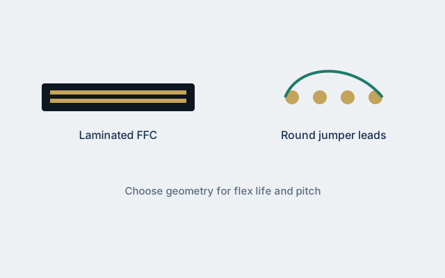
Flexible flat cable (FFC) and jumper leads both move signals through tight spaces, but they are not interchangeable geometries. FFC laminates flat rectangular conductors between films so pitch stays locked for mass termination. Jumper leads — especially the round flexible constructions described in historical SEPM Flat Component materials — behave more like organised discrete wires, sometimes with stainless-core strength for long bending life.
Choosing wrongly shows up late: cracked laminates on a dynamic axis, connectors that will not accept a round bundle, or harness labour that destroys the cost advantage that made FFC attractive on paper. This FFC & Wire Hub guide walks through the decision with OEM-oriented checklists and manufacturer context from archived Malaysian interconnect messaging.
Two geometries, two assembly philosophies
Laminated FFC
- Conductors fixed in pitch order
- One connector stroke can terminate many circuits
- Folds into thin residual height
- Excellent for board-to-board and static or controlled dynamic routes
- Variants: fine pitch (including 0.5 mm class), shielded, Au-plated ends, high-temp / humidity, halogen-free grades
Jumper leads
- Round flexible conductors (or specialised flat rectangular jumpers)
- Routing freedom closer to discrete wire
- Constructions such as stainless-core / tin-plated copper surrounds appear in archived SEPM notes for high-temperature endurance, flame retardance, and long bending life
- Termination may be individual crimps, housings, or custom ends rather than a single FFC connector family
If your manufacturing line is built around FFC connector fixtures, jumping to round leads mid-programme is expensive. If your mechanism needs three-dimensional dressing that fights a laminated ribbon, forcing FFC creates scrap.
Decision drivers that actually matter
1. Flex life and bend radius
Dynamic trailing cables (printer heads, optical sleds, moving sensors) punish sharp creases. FFC can excel when the bend is a controlled single-axis fold within the manufacturer’s radius guidance. Round jumper leads often tolerate more complex motion and torsion — especially with core constructions aimed at bending life.
Ask for cycle life data on your fold path, not a generic catalogue curve. A ribbon that survives 100,000 gentle arcs may fail at 10,000 tight folds against a plastic rib.
2. Pitch and pin count
High pin counts with strict order favour FFC. Once you exceed roughly a dozen circuits and need repeatable pin mapping, laminated ribbons reduce miswire risk. Low pin counts with awkward 3D paths often favour jumpers.
Fine pitch (0.5 mm class SUMI-CARD messaging) amplifies FFC’s value — and its fragility. Handle, fold, and connector wipe forces all become tighter.
3. EMI and shielding
Shielded FFC exists as a product family in SEPM-class archives for scanner-like signal paths. Round jumpers can also be shielded (spiral or braid), but the assembly and connector story changes. Decide EMI strategy before locking geometry.
4. Temperature and environment
Archived jumper-lead notes emphasise high-temperature endurance and flame retardance. FFC high-temp / high-humidity grades address different failure modes (adhesive, insulation film). Match the failure physics: solder-iron adjacency, automotive under-hood adjacent zones, or humid coastal storage each stress materials differently.
5. Assembly labour and automation
FFC wins when automation or semi-automation mates a whole array. Jumpers win when skilled harness builders already exist and volumes do not justify FFC fixture investment. Hybrid designs (FFC on the static span, jumpers on the hinge) appear in mature products — plan the transition connectors carefully.
A practical selection matrix
| Requirement | Lean FFC | Lean jumper leads |
|---|---|---|
| 20+ ordered circuits | Yes | Rarely |
| Single-axis dynamic fold | Often | Sometimes |
| Multi-axis / torsional motion | Caution | Often better |
| Shielded sensor tail | Shielded FFC candidate | Shielded round candidate |
| Existing FFC connector AVL | Strong preference | Costly change |
| Stainless-core bend life story | Not typical | Matches archived jumper notes |
| Ultra-thin residual stack | Strong | Depends on dress |
How SEPM Flat Component materials present both
Public SEPM Flat Component Division messaging historically covers SUMI-CARD™ FFC families and jumper leads in the same product neighbourhood. That pairing is deliberate: OEMs evaluating Malaysian interconnect capacity often need both geometries across a product family. FFC & Wire Hub treats those notes as educational context — see the SEPM brand profile and flat components topic.
Do not assume a plant that laminates FFC automatically stocks your jumper construction, or vice versa. Ask for current capability lists and sample lead times separately.
Mechanical design patterns that reduce risk
For FFC
- Keep folds on designed crease lines; avoid diagonal crumples.
- Support the cable within a few millimetres of the connector to limit peel stress.
- Account for spring-back when the ribbon wants to flatten.
- Protect Au-plated ends from abrasion during assembly.
For jumper leads
- Define minimum bend radii per conductor size.
- Strain-relieve at both terminations.
- Control twist if colour coding or shielding depends on orientation.
- Bundle with materials compatible with your temperature and halogen rules.
For hybrids
- Place the geometry transition on a static board or mid-span connector, not in the highest flex zone.
- Document service loops so field techs do not dress cables into failure.
Electrical notes teams forget
Resistance and inductance differ between flat and round geometries at the same copper cross-section. For power distribution on a ribbon, check voltage drop and heating. For fast edges, impedance and crosstalk depend on pitch, dielectric, and neighbour assignment more than on the marketing name of the cable.
If you migrate from jumper to FFC (or reverse) mid-life, re-validate timing margins and EMC — geometry changes are electrical changes.
Procurement and drawing hygiene
Release separate controlled drawings per geometry. Include:
- Conductor count, AWG or flat conductor size, pitch (FFC)
- Length and tolerance
- Insulation / laminate system and colour
- Termination and plating
- Flex test requirement referencing your mechanism
- Applicable UL/CSA style if the construction is style-recognised
- Substance declarations
When requesting information from SEPM sales channels, prepare application notes as described in How to request SEPM product information. State whether you need FFC, jumper, or both for a module family.
Cost myths to retire
- “FFC is always cheaper.” True at volume with automation; false for low-volume 3D harnesses.
- “Jumpers are always more reliable in flex.” Only if designed and tested for that motion; poor strain relief fails either geometry.
- “Shielded FFC replaces filtering.” It does not.
- “One SEPM catalogue page equals AVL approval.” Quality systems still apply — see later guides on plant certifications.
Validation campaign outline
- Prototype both geometries if the decision is close — cost of two samples beats a tooling regret.
- Run flex life to at least 2× expected service cycles on the production path.
- Pull-test terminations after thermal cycling.
- EMC spot-check if signal integrity or radiation is in scope.
- Time a realistic assembly sequence on the line that will build it.
Capture scrap modes: conductor crack, laminate delamination, insulation abrasion, contact fretting. Feed those modes back into drawing notes.
Related reading
Service and field-replace scenarios
Serviceability changes the geometry vote. FFC that disappears into a sealed optical module may never be field-replaced — factory process quality dominates. Door harnesses, user-accessible sensor wands, or depot-repair boards may favour jumpers that technicians can re-terminate with standard tools.
Write the service story into the design review notes. A geometry that saves thirty seconds on the SMT line can cost thirty minutes in the depot if the only approved repair is “replace entire optical unit.”
Colour, marking, and poka-yoke
FFC often relies on pin-1 marks, blue polyimide tips, or printed legends. Jumpers lean on insulation colours and ring marks. Either way, define poka-yoke so night-shift assembly cannot rotate a connector or swap adjacent circuits. Include marking requirements on the controlled drawing; do not leave them as tribal knowledge on the first pilot line.
When SEPM-class samples arrive with house marking, photograph them and translate the intent into your drawing — sample cosmetics are not a controlled standard.
Thermal paths and current sharing
Flat ribbons spread copper across a wide, thin section; round jumpers concentrate it. For modest power distribution (fans, heaters, LED strings), calculate temperature rise for the geometry you chose. Parallel conductors on FFC need explicit current-sharing rules if you intend to gang them. Jumpers in a bundle can hot-spot in the centre of a tight lace.
Neither geometry forgives undersized copper just because the signal section of the same cable is fine-pitch and elegant.
Programme governance tip
Create a one-page “interconnect geometry decision record” per module: motion class, pin count, connector AVL, EMI, service model, winner, and test evidence link. Store it with the hardware design history file. Six months later, when a cost-down proposal suggests swapping FFC for jumpers (or the reverse), you will know which constraints were binding.
Closing perspective
Jumper leads and FFC solve neighbouring problems with different conductor geometries. Laminated ribbons buy pitch discipline and mass termination; round flexible jumpers buy routing freedom and, in some constructions, exceptional bending life. SEPM’s archived Flat Component story is useful precisely because it presents both under one plant narrative — but your drawing must still pick a geometry for each span.
Make the choice with motion, pin count, connector AVL, EMI, assembly labour, and service reality on the table. Then test the winner on the real mechanism before you freeze the BOM — and keep the decision record so the next cost-down wave does not quietly break a flex-life requirement you already paid to prove.