Guide
Shielded FFC and EMI — when signal paths need a foil layer
Practical guide to shielded flexible flat cable for scanners, cameras, and dense signal routes — how EMI shows up, what shielding adds, and how SEPM-class constructions fit OEM drawings.
16 July 2026
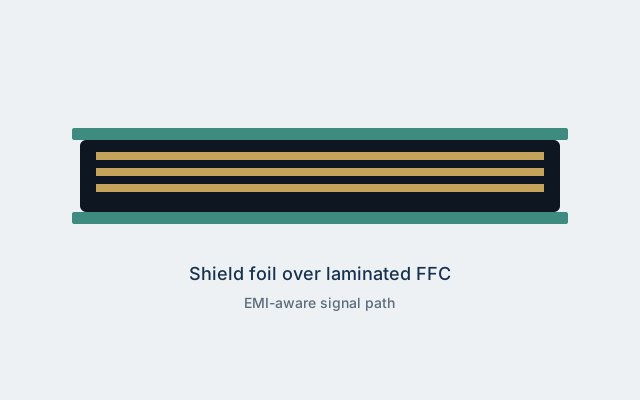
Shielded flexible flat cable (FFC) adds one or more conductive layers around a laminated ribbon so that noise couples less aggressively into (or out of) the conductors underneath. For OEMs packing cameras, scanners, industrial sensors, and high-speed board-to-board links into shrinking chassis, that foil or mesh layer is often the difference between a quiet prototype and a production unit that fails radiated or conducted EMI tests.
This guide explains when shielding is worth the cost and stiffness penalty, how to specify it without over-constraining the supplier, and how publicly archived SEPM Flat Component messaging frames shielded SUMI-CARD™ constructions. It is educational material from FFC & Wire Hub — not a datasheet substitute and not an official manufacturer publication.
Why EMI shows up on flat cable first
Flat cable is efficient at packing many signals into a thin stack. That same geometry creates a relatively large parallel plate area between conductors and nearby metal, and between conductors themselves. When edge rates rise — camera clocks, USB-class differentials adapted onto FFC, ADC strobes, motor encoder pulses — the ribbon becomes both a victim antenna and a radiator.
Common failure modes in OEM labs include:
- Victim coupling — a noisy switching rail or motor drive inductively or capacitively couples into an adjacent analogue or clock pair on the same FFC.
- Common-mode radiation — return currents leave the intended ground plane, travel on the cable shield or on chassis bonds, and radiate.
- Connector discontinuity — a beautifully shielded cable that dumps its shield onto a floating shell at the connector undoes most of the benefit.
- Ground bounce shared with digital returns — dense FFC pinouts that interleave power, ground, and signals poorly can amplify bounce even before EMI chambers are booked.
Shielding does not fix a bad pinout by itself. It does reduce field coupling to the chassis cavity and neighbouring harnesses when the shield is terminated correctly at both ends (or deliberately at one end for specific low-frequency strategies).
What “shielded FFC” usually means in practice
Archived Sumitomo / SEPM Flat Component language describes shielded SUMI-CARD™ for EMI-sensitive paths such as scanner signal cabling. In practical OEM drawings, that typically means:
- A laminated FFC core (flat rectangular conductors between insulation films)
- One or more conductive shield layers (foil, metallised film, or similar)
- Insulation or jacket layers that keep the shield from shorting unintended surfaces
- Prepared ends that expose conductors for the connector while providing a defined shield termination method
Exact constructions vary by pitch, temperature grade, plating, and halogen-free goals. Treat marketing family names as a conversation starter: your controlled drawing must still call out pitch, conductor count, length, fold plan, plating, shield type, and termination.
When to prefer shielded FFC over discrete wire or rigid-flex
Choose shielded FFC when you need ordered mass termination, repeatable fold geometry, and moderate EMI control without jumping straight to a custom rigid-flex stack-up.
| Situation | Likely fit |
|---|---|
| Scanner / CIS / CIS-like sensor tails | Shielded FFC often appears in historical product notes |
| Short board-to-board with quiet analogue neighbours | Shielded FFC or careful pinout + ground stitch |
| Very high flex cycle life with heavy EMI | Evaluate specialty constructions; may need discrete shielded pairs |
| Extreme density / impedance control | Rigid-flex or micro-coax may win despite cost |
Cost and stiffness rise with shielding. Dynamic printer-style trailing cables sometimes stay unshielded if the mechanical life requirement dominates and system-level shielding (chassis, filters) carries the EMI budget. Static or semi-static sensor tails more often justify foil layers.
Specifying shield termination — the step teams skip
A shield that is not bonded is decoration. Your drawing should answer:
- Bond both ends or one end? Both-end bonds help high-frequency return paths; single-end bonds are sometimes used to avoid ground loops at lower frequencies. Pick deliberately with the EMC engineer.
- Where does the bond land? Connector shell, PCB ground pad, chassis stud? Document torque or solder process if relevant.
- Is the shell continuous through the mating connector? Many FFC connectors have limited shield provisions — validate the connector family early.
- How is drain / foil folded at the prepared end? Fold-back length and insulation keep-out zones matter for fixture tooling.
If SEPM or another Malaysian plant quotes a shielded SUMI-CARD-class part, ask for the termination sketch used in their standard samples, then adapt it to your connector — do not assume the sample fold matches your housing.
Pitch, plating, and shield — interactions that bite
Fine-pitch FFC (including 0.5 mm options highlighted in SEPM-class materials) leaves less copper width per conductor and less room for creative ground stitching. Shielding becomes more attractive precisely when pitch is tight and analogue signals sit near clocks.
Gold plating on contacts improves corrosion resistance and contact reliability; it does not replace a shield. Combine Au-plated ends with shielding only when both contact life and EMI budgets demand it — each option adds cost and lead-time risk.
High-temperature or high-humidity grades change insulation systems; confirm the shield adhesive and foil still meet your temperature profile after lamination. Halogen-free “HIGH-rating” style messaging in archives is about substance and flame goals — still verify with current declarations.
Design checklist before you release the drawing
- List aggressors and victims on the same ribbon (clocks, switches, ADC inputs, reset lines).
- Assign pinout with grounds flanking sensitive pairs where connector rules allow.
- Decide shield strategy (foil type, both-end vs single-end bond).
- Pick connector family that can actually terminate the shield.
- Define bend radius and fold plan so the foil does not crack at crease lines.
- Call out length tolerance — shielded constructions can have different shrink behaviour.
- Plan EMC pre-compliance with the cable installed as in production, not floating on a bench.
- Request substance docs (RoHS, halogen, customer blacklist) alongside the mechanical drawing.
How SEPM archives frame the story
SEPM’s Flat Component Division messaging historically stresses thinner cables, finer pitches, and shielded constructions for EMI-sensitive scanner paths. That does not mean every SEPM FFC is shielded, and it does not mean FFC & Wire Hub can quote live SKUs. Use the SEPM brand profile for plant context and archived phones, and treat product topic pages such as SUMI-CARD™ and flat components as orientation.
For Malaysian sourcing programmes, long FFC heritage (public milestones place FFC production at Tebrau II in the early 1990s) is a capacity signal. Capacity is not the same as an approved vendor list entry — your quality team still needs PPAP-like evidence or incoming inspection plans appropriate to your industry.
System-level EMI hygiene that still matters
Even with a shielded ribbon:
- Keep return paths short on the PCB near the connector.
- Filter power that rides the same FFC.
- Avoid routing the cable across slot antennas in the chassis.
- Clamp cables so vibration does not fretting-corrode shield bonds.
- Re-test after cosmetic housing changes — paint and gaskets alter cavities.
Shielded FFC is one control among many. It shines when the cable is the coupling path you can afford to treat without redesigning the entire PCB.
Procurement language that reduces churn
Instead of “need shielded FFC like SEPM scanner cable,” write:
Flexible flat cable, X conductors, Y mm pitch, length Z mm ± tolerance, shielded construction with foil terminated to connector shell at both ends per sketch A, operating −20 °C to 85 °C (example), Au-plated contacts if required, halogen-free if required, UL recognition if required, sample of 20 pcs for EMC and flex validation.
Attach the fold sketch. Mention reference families (SUMI-CARD shielded class) only as examples of construction intent.
Validation plan for the first builds
- DC continuity and insulation resistance on every conductor and shield.
- Flex life on the production fold path (not a gentle lab arc).
- Near-field probe along the cable during worst-case traffic.
- Full radiated/conducted tests with production shield bonds.
- Thermal soak if the foil adhesive is new to your AVL.
Document failures with photos of termination quality — most “shield didn’t help” tickets trace to open bonds or paint-insulated shells.
Related reading on this site
- Flexible flat cable basics for OEMs
- SUMI-CARD™ pitch options
- Flat components & FFC topic
- How to request SEPM product information
Field failures worth photographing
When a shielded FFC “does nothing” in the chamber, capture evidence before swapping parts:
- Continuity from foil to shell at both ends (or the single designed end)
- Paint, powder coat, or anodise insulating the intended bond pad
- Foil cracked at a fold that looked fine at room temperature but opened after thermal cycles
- A service loop that staff dressed across a chassis slot acting as an antenna
- Mixed revisions: unshielded samples left in a shielded BOM line
Those photos shorten debates between electrical, mechanical, and contract manufacturers. They also feed supplier corrective action when a lot arrives with inconsistent fold-back length.
Working with contract manufacturers in ASEAN
Many programmes assemble in Malaysia, Vietnam, or Thailand while sourcing interconnect from Johor or other regional plants. Align three documents early: the OEM controlled drawing, the cable maker’s construction sketch, and the CM’s work instruction for shield bonding. Language gaps around “secure the shield” create latent EMI escapes that only appear after tooling is paid for.
If you reference SEPM-class shielded SUMI-CARD constructions in RFQs, attach your fold sketch anyway. Regional suppliers often have multiple foil stacks that all market as “shielded.” Your sketch is the requirement; the family name is orientation.
Budgeting time in the project plan
Add explicit tasks — not tribal knowledge:
- Connector + shield feasibility (week of architecture freeze)
- Sample cable with production-intent termination (before PCB fab of EMI candidate)
- Near-field probe on functional sample
- Pre-compliance with production bonds
- Incoming inspection criteria for foil continuity on production lots
Skipping step 2 is the most common schedule killer: boards arrive ready for EMI while cables are still “similar to sample.”
Closing perspective
Shielded FFC is not a magic foil wrapper. It is a disciplined way to keep laminated, mass-terminated interconnects compatible with modern EMI limits when scanners, cameras, and dense signal tails share a chassis with switching noise. Specify the shield and its termination as carefully as pitch and length, validate on the real mechanical path, and use manufacturer brand notes — including SEPM’s archived Flat Component story — as context rather than as a substitute for controlled drawings.
When your next design review asks whether the ribbon needs a shield, answer with aggressors, victims, connector reality, and a test plan — not with a vague hope that “industrial cable” will quiet the chamber on its own. Document the bond, prove it on the production fold, and keep the foil honest with incoming checks so the quiet prototype stays quiet in volume.